Electrical Signals
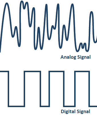
In the world of electronics there are two major types of signals:
- Analog
- Binary (or Digital)
An electronic analog signal varies over time and can have a different value at any given time.
An electronic binary signal can also vary over time, but it can only be used to represent two separate levels.
The digital circuits that make up all modern computers use binary signals for communication and for information storage.
Why Binary?

Some reasons for why modern computers use binary signals (as opposed to analog signals):
- Binary is very simple compared to analog.
- This simplicity means binary circuits are easy to build.
- Flawless copies of binary signals can be made.
- Anything that can be represented with some sort of finite pattern can be represented with a pattern of binary bits.
In electronic circuits binary zero is represented by a low voltage (near zero volts) and binary 1 is represented by a high voltage (often five volts).
Boolean Logic

Boolean logic is a type of algebra where the variables can only take two possible values. These values are 1 and 0, although we sometimes refer to these as true and false respectively. In other words, Boolean logic is an algebra for binary systems.
As we saw in the history module, Boolean logic was developed by George Boole in the 1840s and was later implemented electronically by Claude Shannon (right) in the 1930s, leading to the advent of electronic computers.
At the heart of nearly all electronic circuits lies this system of Boolean calculation.
Digital Logic
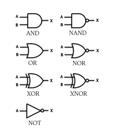
Instead of studying Boolean algebra on it’s own, we will study the digital components used in electronic circuits that implement Boolean algebra operations.
These components are called digital logic gates. We will be using the symbols shown to the right to represent these gates.
The lines leading to the left of each gate represent input wires, while the line leading from the right of each gate represents the output.
You can think of each gate as performing an algebraic operation on its inputs to create its output. The inputs and outputs will always be the binary values of either true or false.
Simply Boolean System

Imagine a house with a doorbell. When the doorbell button is pressed a chime will be heard within the house.
We can model this as a Boolean system:
- Doorbell button pressed = Binary 1
- Doorbell button unpressed = Binary 0
(Doorbell Chime) = (Doorbell button pressed)
Another Boolean System

Many cars will signal a buzzer if the engine is on and the driver’s seat-belt is undone.
Modeled as a Boolean System:
- Engine: On/Off
- Seat-belt: Undone/Fastened
Buzzer = (Engine is On?) AND (Seat-belt is Undone?)
Stated another way:
Buzzer = (Engine is On?) AND (Seat-belt is NOT Fastened?)
NOT Gate
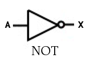
The simplest logic gate is the NOT gate, sometimes called an inverter.
- It has one input and one output.
- The output is always the opposite of the input.
The truth table for a NOT gate:
| A | X |
---------
| F | T |
| T | F |
In other words, X is true when A is NOT true.
AND Gate
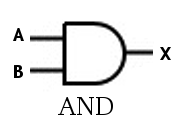
An AND gate has two inputs and one output.
The output is always false, unless both inputs are true.
The truth table for an AND gate:
| A | B | X |
-------------
| F | F | F |
| F | T | F |
| T | F | F |
| T | T | T |
In other words, X will be true when both A AND B are true.
Does this truth table look familiar? (Hint: Compare it to our selt-belt example.)
Resources
Wikipedia Links:
OR Gate
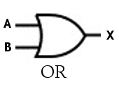
An OR gate has two inputs and one output.
The output is always true, unless both inputs are false.
The truth table for an OR gate:
| A | B | X |
-------------
| F | F | F |
| F | T | T |
| T | F | T |
| T | T | T |
In other words, X will be true when both A OR B are true.
XOR Gate
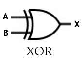
An XOR gate has two inputs and one output.
The output is true, unless both inputs are the same.
The truth table for an XOR gate:
| A | B | X |
-------------
| F | F | F |
| F | T | T |
| T | F | T |
| T | T | F |
In other words, X is true when A is NOT equal to B.
Negated Gates
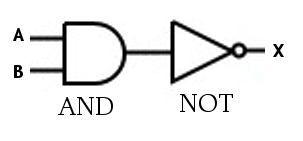
It is common in digital circuit design for a NOT gate to follow directly after one of the other gate types.
To simplify our circuit diagrams there are a series of negated gates to use in this situation.
NAND Gate
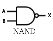
A NAND gate has two inputs and one output. It is equivalent to an AND gate followed by a NOT gate.
The output is always true, unless both inputs are true.
The truth table for an NAND gate:
| A | B | X |
-------------
| F | F | T |
| F | T | T |
| T | F | T |
| T | T | F |
NOR
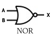
A NOR gate has two inputs and one output. It is equivalent to an OR gate followed by a NOT gate.
The output is always false, unless both inputs are false.
The truth table for an OR gate:
| A | B | X |
-------------
| F | F | T |
| F | T | F |
| T | F | F |
| T | T | F |
XNOR
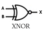
An XNOR gate has two inputs and one output. It is equivalent to an XOR gate followed by a NOT gate.
The output is true, when both inputs are the same. For this reason it is sometimes called an equality gate.
The truth table for an XNOR gate:
| A | B | X |
-------------
| F | F | T |
| F | T | F |
| T | F | F |
| T | T | T |
Systems of Gates
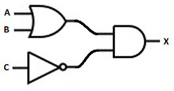
Gates can be chained together to create more complex structures.
The truth table for the system to the right:
| A | B | C | X |
-----------------
| F | F | F | F |
| F | F | T | F |
| F | T | F | T |
| F | T | T | F |
| T | F | F | T |
| T | F | T | F |
| T | T | F | T |
| T | T | T | F |
In other words, X will be true whenever A OR B is true unless C is true.
A friendlier way to look at this truth table would be to change the positions of columns and replace the T/F for 1/0:
| C | A | B | X |
-----------------
| 0 | 0 | 0 | 0 |
| 0 | 0 | 1 | 1 |
| 0 | 1 | 0 | 1 |
| 0 | 1 | 1 | 1 |
| 1 | 0 | 0 | 0 |
| 1 | 0 | 1 | 0 |
| 1 | 1 | 0 | 0 |
| 1 | 1 | 1 | 0 |
Here it is more obvious that X is false anytime C is true, and that when C is false X will be true if either A or B is true.
How would the truth table change if the OR gate was replaced by an XOR?